 English
 Español
 Português
 Русский
 عربي
عربي Türkçe
 Deutsch
 Polski
 Français
 Italiano
 Tiếng Việt
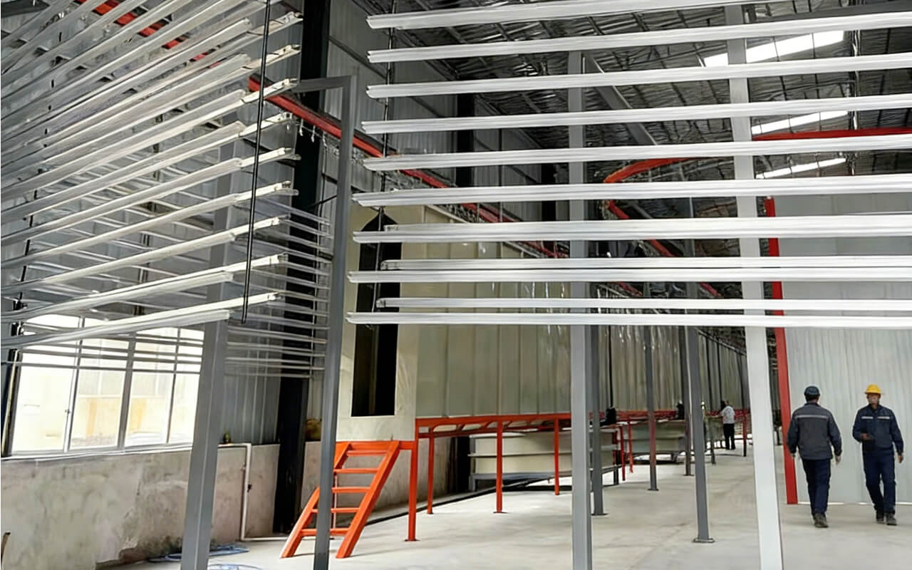
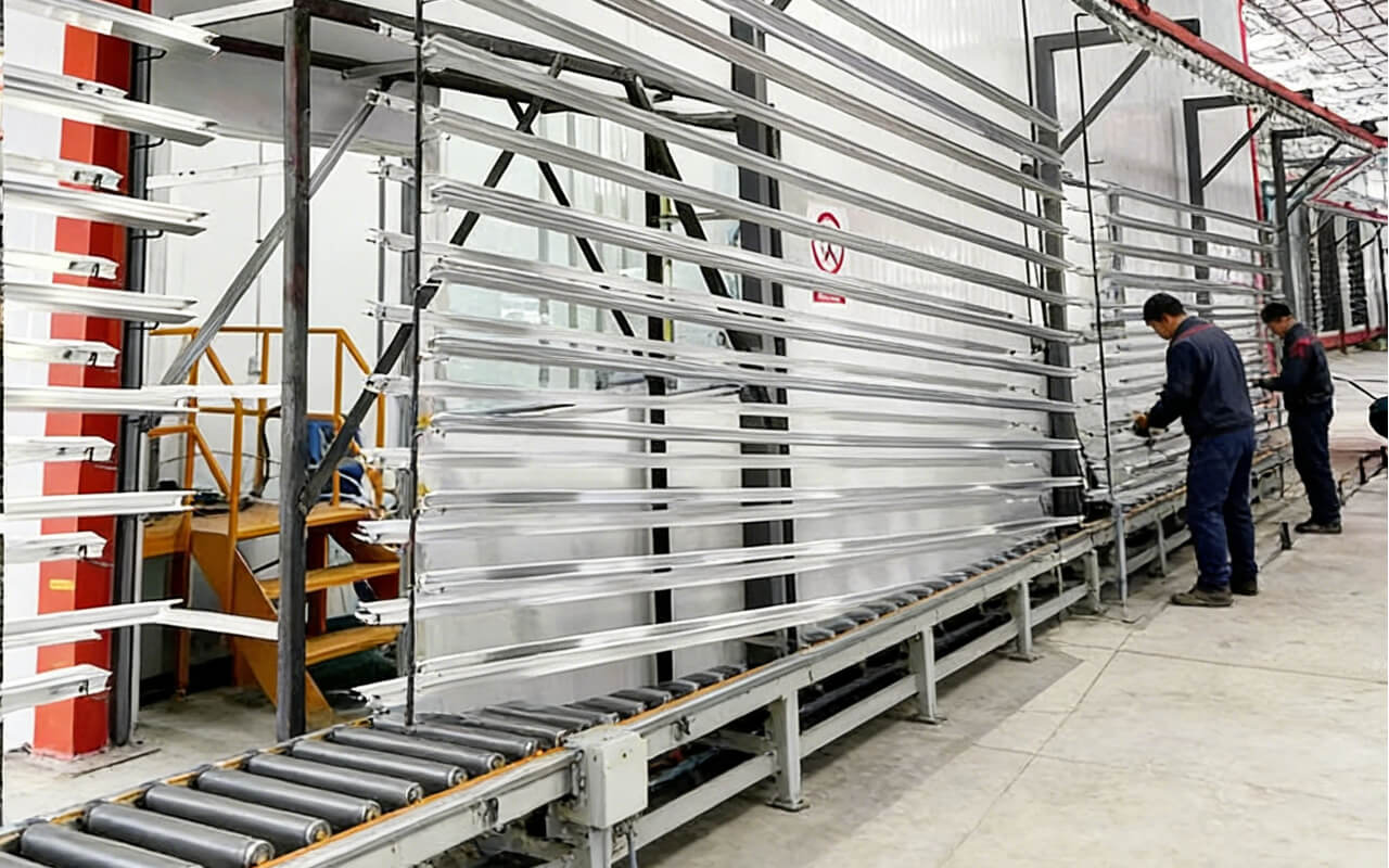
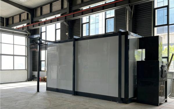
Alüminyum Profil Yarı Otomatik Toz Boyama Sistemi
ST-MPCL7315


Fiyat: USD10000~20000
Teklif Al PDF
Yüksek Kapasiteli Kürleme: Çok sayıda iş parçasını işleyebilen yüksek kapasiteli bir kürleme fırını içerir ve yüksek verimlilik sağlar.
Kompakt Boyut: Kompakt tasarımı sayesinde sınırlı alana sahip fabrikalar için uygundur ve seri üretim için idealdir.
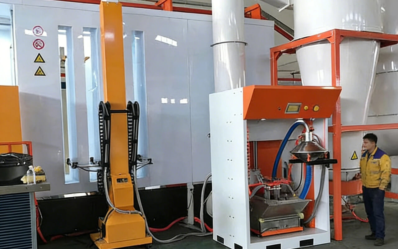
Standart bir kurulum şunları içerir: Bir takım manuel kaplama ekipmanı; Filtre geri kazanım sistemli, içine girilebilen bir toz boyama kabini; Gaz tipi bir kürleme fırını; Bir taşıma ray sistemi.
Sorunsuz Proses Entegrasyonu: Ön işlem, püskürtme, düzleme, kurutma ve soğutmayı tek bir sürekli iş akışında birleştirerek homojen ve yüksek kaliteli yüzeyler elde edilmesini sağlar.
Toz boyalı alüminyum profiller, dayanıklı ve estetik açıdan hoş bir görünüm sunar. Kaplama, asitlere, alkalilere, darbelere, aşınmaya ve uzun süreli hava koşullarına (güçlü UV ışınları ve asit yağmuru dahil) karşı son derece dayanıklı, pürüzsüz ve düzgün bir yüzey sağlar; tebeşirlenme, solma veya soyulma yapmaz. Sıradan alüminyuma kıyasla üstün korozyon ve hava koşullarına dayanıklılığının yanı sıra, çok çeşitli renklerde de mevcuttur.
Endüstri için kaplama çözümleri
This production line consists of pre-treatment equipment, drying, powder spraying, powder curing, an overhead conveyor system, and an electrical control system.
Note: Secondary combination hangers and other accessories are to be provided by the clients.
I Technical Parameters
|
No. |
Name |
Design Basis |
|
1 |
Product Name |
Aluminum Profile |
|
2 |
Product Material |
Aluminum |
|
3 |
Material Thickness |
Less than 5.0 mm |
|
4 |
Pretreatment Method |
Spray |
|
5 |
Surface Coating Method |
Powder |
|
6 |
Coating Surface of Workpiece |
External Surface |
|
7 |
Max Hanging Dimensions of Workpiece |
L7000 *W300 *H1500 |
|
8 |
Hanging Method |
Double-Point Hanging |
|
9 |
Maximum Weight of Workpiece |
≤50 kg |
|
10 |
Conveyor Chain |
QXG-250-50KG Light-Duty Conveyor Chain |
|
11 |
Production Capacity |
1000 kg/day |
|
12 |
Hanging Spacing |
|
|
13 |
Process Speed (Determined by client) |
1.0 m/min |
|
14 |
Speed Adjustment Range |
0.2–2 m/min |
II Process Flow
Production Line Process Flow: Uploading → Powder Coating → Powder Curing → Cooling → Unloading
III Equipment Configuration
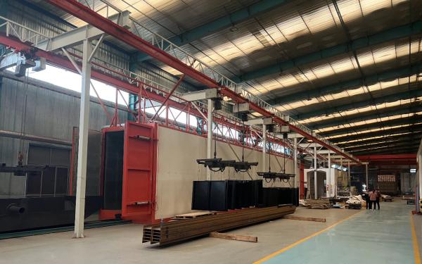
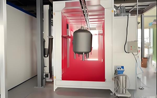
1. Powder Drying Oven: 1 set
Its structure and dimensions are as follows:
External dimensions: L30.0m × W1.20m × H4.0m. For details, refer to the cross-sectional diagram in the plan.
The drying chamber adopts a "sandwich" insulation panel assembly structure. The air supply ducts inside the chamber are made of δ1.2 galvanized steel sheets. The outer panels of the insulation boards are made of δ0.60 color steel sheets, while the inner panels are made of δ0.60 galvanized steel sheets, with embossing on both sides. The insulation layer has a thickness of 120mm. The drying chamber employs a hot air circulation heating method. Its advantage lies in the uniform temperature distribution within the chamber, with a temperature difference of less than ±8°C between the upper, middle, and lower points along the cross-section of the track, thereby ensuring consistency in the color of the workpiece coating.
The drying tunnel adopts natural gas heating method;
The curing drying tunnel is equipped with: one 500,000 kcal unit.
The specific parameters of the curing tunnel are as follows:
|
No. |
Name |
Parameters |
|
1 |
Overall structural Type |
Box |
|
2 |
External cavity dimensions |
L30.0m×W1.20m×H4.0m |
|
3 |
Thickness of insulation layer |
120mm |
|
4 |
Insulation material |
High-quality rock wool board |
|
5 |
Density of insulation material |
120Kg/m3 |
|
6 |
Inner panel material of curing oven insulation board |
δ0.60mm galvanized steel sheet with ribs |
|
7 |
Outer panel material of curing oven insulation board |
δ0.60mm color steel sheet with ribs |
|
8 |
Air supply duct and outlet |
δ1.2mm galvanized sheet |
|
9 |
Average surface temperature of drying room |
Not exceeding ambient temperature by 10°C |
|
10 |
Heating of drying room |
Time to reach 120°C ≤ 30min |
|
11 |
Heating chamber power |
Natural gas 500,000 kcal, 1 set; Burner: Riello RS50 dual-stage fire |
|
12 |
Circulation fan |
4-72-6C 11KW; 1 unit |
|
13 |
Exhaust pipeline |
1 set (galvanized steel sheet, directly rising from the side of the workshop to the roof) |
|
14 |
Bridge frame columns and framework of drying room |
Various shapes made from δ2.5 hot-rolled plate with folded edges, and 75×50 special-shaped angle steel as the base plate |
|
15 |
Upper and lower corner protectors of drying room |
Upper corner protector made of δ2.5mm carbon steel, lower corner protector made of δ2.5mm carbon steel plate, with paint treatment |
2.Conveying System
The QXG-250-50Kg conveyor is selected for the system.
Chain Pitch: 250mm;
Single Point Lifting Capacity: 50Kg;
Process Speed: 1.00 m/min;
Adjustment Range: 0.2–2.0 m/min;
Speed Control Method: Frequency conversion speed control;
The total length of the overhead conveyor chain is 120m, utilizing one drive unit and one tensioning device. The tensioning device employs a counterweight tensioning mechanism. Emergency stop switches are installed at necessary locations along the entire line, specifically at the loading point, unloading point, and near the powder spraying chamber. The curing oven is equipped with thermal expansion joints.
To enhance the service life of the conveyor, all curved tracks are made of manganese steel, and the turning radius is maximized wherever possible.
The conveyor chain features a bidirectional hinge design with a double chain plate structure. Its traveling wheels and guide wheels are ball-type rollers, arranged alternately with double guide wheels and single guide wheels to minimize track wear. The supplier provides both single and combined hangers.
The parameters of the conveyor are as follows:
|
No |
Name |
Parameters |
|
1 |
Drive Unit Model |
QXG-250 |
|
2 |
Quantity of Drive Units |
1 set |
|
4 |
Overload Protection of Drive Unit |
Adjustable Safety Clutch + Limit Switch |
|
5 |
Power of Drive Unit |
3.0KW |
|
6 |
Type of Tensioning Device |
Counterweight Tensioning |
|
7 |
Quantity of Tensioning Devices |
R3500mm,1 set; |
|
8 |
Structure of Conveyor Chain |
Double-directional hinged, suitable for horizontal and vertical turns |
|
9 |
Length of Conveyor Chain |
Total 120m |
|
10 |
Pitch of Conveyor Chain |
250mm |
|
11 |
Single Point Lifting Capacity of Conveyor Chain |
50Kg |
|
12 |
Process Speed of Production Line |
1.00m/min; |
|
13 |
Speed Adjustment Range of Production Line |
0.2~2.0m/min |
|
14 |
Speed Adjustment Method of Production Line |
Variable Frequency Speed Control |
|
15 |
Lubrication Device |
Automatic Spray Lubrication |
|
16 |
Quantity of Lubrication Devices |
1set(No oil dispenser for the drive unit after pre-treatment) |
|
17 |
Steel Structure of Overhead Conveyor |
100*100 square tube, #8 channel steel, painted |
|
18 |
Oil Drip Pan |
Included |
|
19 |
Secondary Hanger (Lifting Hook) |
Provided by the customer |
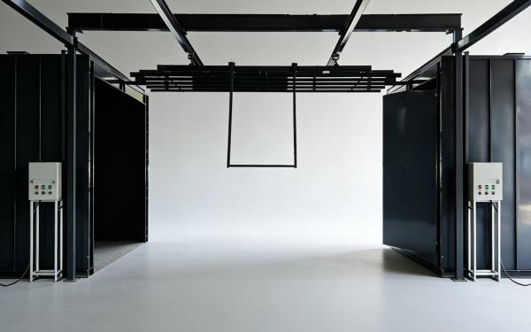
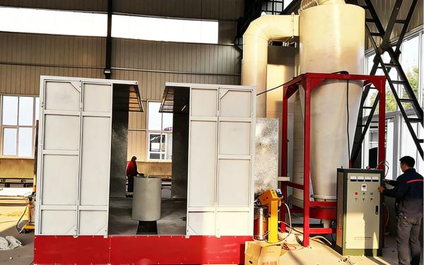
3.The Spraying Booth
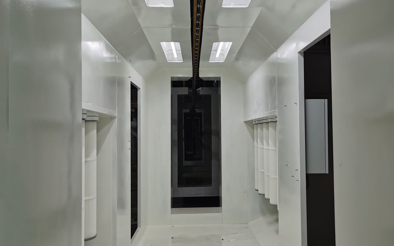
(1) Manual Powder Spray Booth Description:
The powder spray booth is an enclosed space where powder coating operations are performed on workpieces. The structure and airflow design of the spray booth are crucial to the powder coating process. Based on the process requirements of the production line workpieces, the powder spray booth has the following features:
① Powder spray booth dimensions: 6.0*1.60*2.80 meters (length * width *height)
② Each side of the spray booth is equipped with a manual powder spray opening.
③ The wall panels and roof panels of the booth are made of cold-rolled steel plates. The inner surface of the booth is smooth and clean, with sealant applied between panel seams to ensure no powder leakage. Powder cleaning is convenient and easy.
④ The entrance and exit of the spray booth feature an arc-shaped structure with ear channels, ensuring smooth movement of workpieces in and out while minimizing the opening area of the booth. The design is aesthetically pleasing and effectively prevents powder overflow.
⑤ The top of the spray booth and the manual repair door are equipped with quick-replacement fluorescent lamps, ensuring sufficient lighting inside the booth.
⑥ The bottom of the booth is flat, making powder cleaning convenient.
⑦ The spray booth utilizes side-bottom ventilation and an equalizing pressure device, ensuring rational airflow organization inside the booth. The airflow is gentle, increasing the retention time of powder in the booth to improve powder adhesion efficiency. This reduces the load on the recovery system and extends its service life. Color change and powder cleaning are cleaner and faster, with a major color change and powder cleaning time of within 45 minutes.
⑧ All air pipes are connected with quick couplings, making disassembly and assembly simple and enabling fast color changes.
(2) Effective Indicators of the Powder Spray Booth:
|
No |
Item |
Specification |
|
1 |
Overall Dimensions |
L6000*W1600*H2800(mm) |
|
2 |
Workpiece Entry/Exit Dimensions |
W1000mm*L1600mm |
|
3 |
Recovery Method |
Cartridge Recovery |
|
4 |
Type |
Through Double-Sided type Spraying |
|
5 |
Compressed Air |
0.5-0.7MPa |
|
6 |
Open Face Velocity |
0.5m/sec |
|
7 |
Exhaust Air Volume |
14000 m3/h |
|
8 |
Spraying Method |
Manual Powder Spray Gun (Dual-Station Layout for Right and Wrong Sides) |
|
9 |
Installed Power of Equipment |
15kW |
(3)Material Usage in the Powder Spray Booth
|
No |
Name |
Specification |
|
1 |
Side Wall Panels and Roof Panels of the Booth |
Galvanized Sheet δ=1.2mm |
|
2 |
Floor Plate of the Booth |
Galvanized Sheet δ=1.5mm |
|
3 |
Inlet and Outlet Ports |
Galvanized Sheet δ=1.2mm |
|
4 |
Floor Support |
Hot-Rolled Steel Plate δ=2.5mm |
|
5 |
Light Box |
Galvanized Sheet δ=1.2mm |
|
6 |
Recovery Tank |
Galvanized Sheet δ=1.2mm |
|
7 |
Recovery Fan |
7.5kW Centrifugal Fan, 2 units in total |
|
8 |
Filter Element |
Quick-Release Type 3290, 16 units in total |
|
9 |
Air Duct |
0.7mm Galvanized Sheet |
|
10 |
Lighting |
40W Fluorescent Lamp |
(4)Secondary Filtration Recovery Cabinet
|
No. |
Name |
Specification |
|
1 |
Chamber Side Wall Panel and Top Panel |
Galvanized Sheet δ=1.2mm |
|
2 |
Support Frame |
Square Tube 100*2.0 |
|
3 |
Filter Element |
Quick-release Type, 3290, Total 9 |
|
4 |
Air Duct |
0.7MM Galvanized Sheet |
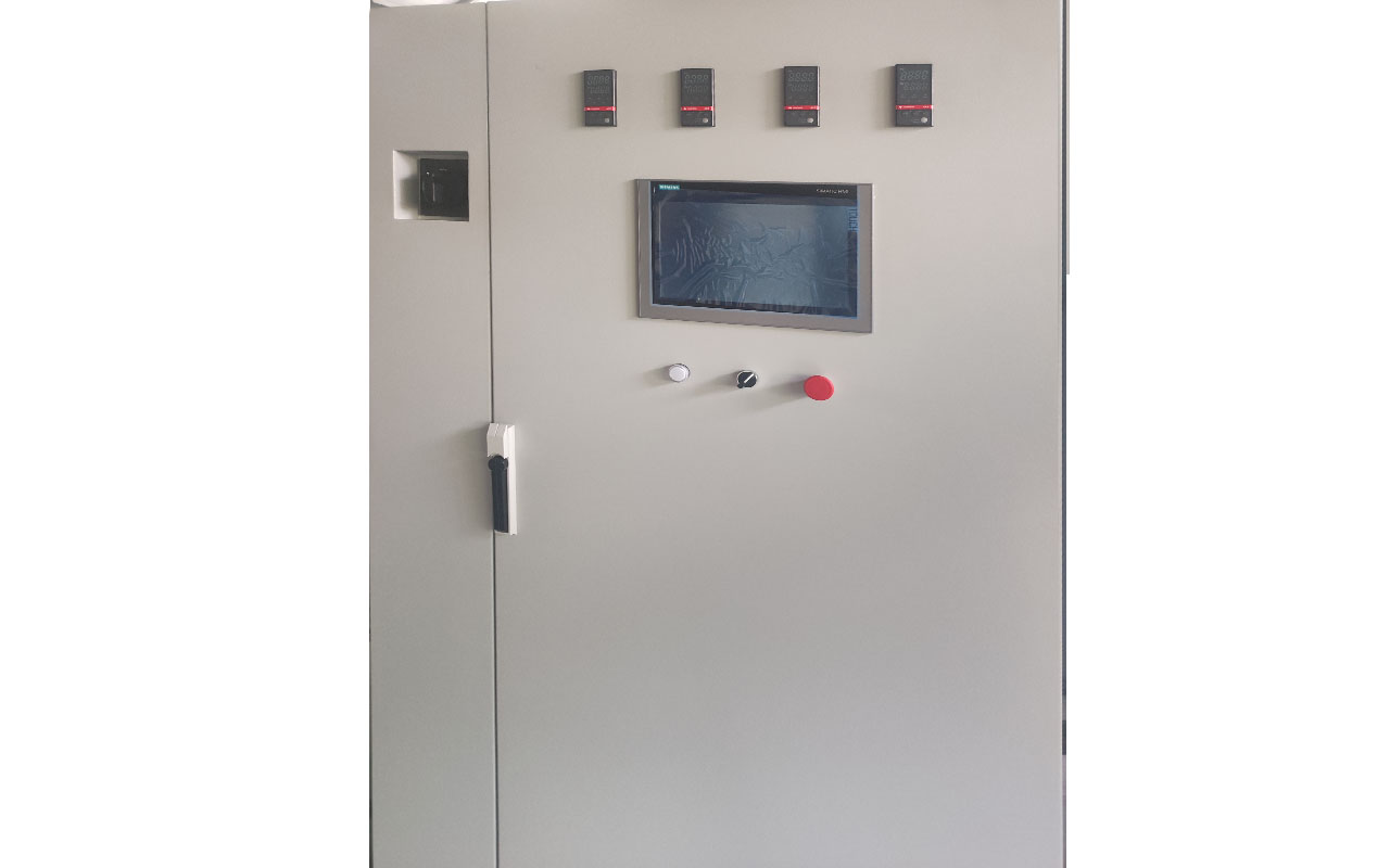
4. Electrical Control System 1 set
4.1 This system includes all control boxes, wires, cables, conduit pipes, cable trays, etc., used in the electrical control system.
4.2 The main electrical control system adopts a combination of centralized and decentralized control via electrical cabinets. Conventional operations such as start/stop and temperature control can be performed on the electrical cabinets of each device.
4.3 All electrical cabinets are equipped with a three-level protection system, including a main power air switch, branch circuit air switches, and thermal relays. This effectively protects against short circuits, overloads, and phase failure faults, while sending alarm signals to the host computer.
4.4 All motors with a power exceeding 11 kW utilize a Y-Δ (star-delta) starting method.
4.5 The temperature control in the drying oven uses platinum thermal resistance sensors for temperature measurement and digital display temperature controllers to regulate the combustion chamber. A dual temperature control protection system is employed: the temperature controller maintains the stability of the furnace temperature, while the overtemperature controller is typically set 10–15°C above the furnace temperature. If a system malfunction causes the furnace temperature to exceed the control value and reach the overtemperature control value, all heaters will be forcibly shut off, and an alarm signal will be triggered.
4.7 An electrical interlock protection is implemented between the drying oven's circulation fan and the heaters, supplemented by an air pressure switch protection. The heaters can only be activated after the fan is started and the fan impeller is confirmed to be operating. Regardless of whether the fan is manually or protectively shut down, the heaters will delay for 20–30 minutes before turning off to ensure sufficient cooling of the heat exchanger.
4.9 The following abnormalities will be indicated on the pretreatment control cabinet, with alarm lights activated and an audible alarm triggered:
4.10 Upper/Lower Liquid Level Abnormalities—Exceeding the upper or lower liquid level limits of each tank.
4.11 Temperature Abnormalities—The temperature of the heating process liquid exceeds the set value.
4.12 Overload—The current value of the motors for each pump and fan exceeds the set value.
4.13 Other necessary items for abnormality detection. (Alarm stop switches and abnormality reset switches are installed on the control panel.)
IV Energy Consumption Table:
|
No |
Item |
Consumption |
||
|
1 |
Water Consumption |
Average: 3.00 T/h |
||
|
2 |
Electricity Usage |
Powder Drying Oven |
12KW |
|
|
Overhead Conveyor |
4.0KW |
|||
|
Powder Spray Booth |
15.0KW |
|||
|
Installed Power |
Approx.31KW |
|||
|
3 |
Natural Gas |
Max 50m³ |
|
|
İlgili Ürün
ST-MPCL6120
Elektrikli Isıtma Fırını Sprey Boyama Ekipmanı
ST-MPCL6010
Manuel Metal Toz Boyama Hattı

ST-MPCL2914
Manuel Boya Üretim Hattı
ST-MPCL6032


