 English
 Español
 Português
 Русский
 عربي
عربي Türkçe
 Deutsch
 Polski
 Français
 Italiano
 Tiếng Việt
How Does a Spray-Painting Robot Decide Where to Apply More Coat — and Where Less?(1)
Traditional manual spraying relies on "feel" — a seasoned painter intuitively knows where to lay on an extra pass and where to glide through lightly. When it comes to spray robots, that "feel" becomes an "algorithm." So how do you make a machine as smart as the old master?
Behind the answer is a complete closed-loop decision chain: 3D visual perception → surface geometry analysis → film-thickness distribution modeling → real-time feedback and correction. This article breaks down how that "brain" actually works.
I. From "Uniform" to "Appropriate" — Why Differentiated Film Thickness Matters
Many people's first impression of a spray robot is that it "sprays more evenly than a human" — but this is only half right. The robot's real advantage is not "averaging" — it's on-demand allocation.
"Uniform film thickness" ≠ "Appropriate film thickness"
Different areas of the same workpiece can have dramatically different coating requirements:
- Simply put: spraying every zone the same thickness is laziness; spraying each zone exactly what it needs is intelligence.
II. Five Decision Criteria — How Does the System "Know"?
An intelligent spray system doesn't make decisions based on a single piece of information. It relies on multi-modal data fusion across five dimensions:
| Criterion | Data Source | What It Tells the System | Typical Output | Priority |
|---|---|---|---|---|
| ❶ CAD Design Specs | CAD/3D model files, film-thickness spec sheets | "What the designer wants" | Zone-specific target thickness: exterior 120±20 μm, inner cavity 80±15 μm, flange edge 50–70 μm | Baseline |
| ❷ Visual Perception | 3D camera / laser scan / structured light | "What the workpiece actually looks like" | Real surface point cloud, curvature map, edge contours, opening/cavity recognition | Correction |
| ❸ Process Database | Historical spray data, process knowledge base | "How similar parts were sprayed before" | Recommended starting parameters: flow rate / voltage / gun distance / trajectory speed | Reference |
| ❹ Wear Prediction | Operating conditions, service-life models | "Where is the part most likely to fail over time" | Extra compensation for windward face / stone-chip zones / water-pooling areas / sharp edges (+10–30 μm) | Reinforcement |
| ❺ Functional Zoning | Product function definitions, assembly relationships | "Which areas have special requirements" | Assembly surfaces need reduced thickness / conductive surfaces need continuity / sealing surfaces need specific roughness | Hard constraint |
Core logic: CAD design is the "base map," vision provides "corrections," the database gives the "starting position," wear prediction adds a "safety margin," and functional zoning sets the "hard limits."
The five factors are not simply stacked — they are weighted and fused. Visual data carries the highest real-time weight (because a workpiece can shift or deform), the CAD film-thickness targets set the floor (anti-corrosion requirements cannot be undercut), and functional zoning is the absolute red line (assembly interference is worse than a thickness overrun).
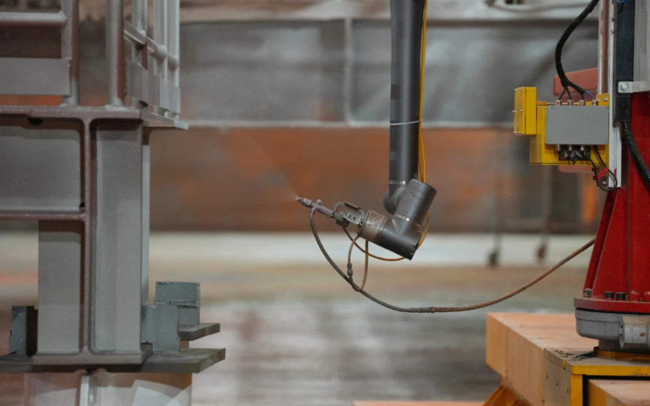
III. 3D Vision — "Seeing" the Workpiece Surface Is Just the First Step
In the previous article "The Eyes of the Spray Robot", we broke down how the visual system is mounted and how it forms images. In the context of film-thickness decisions, the vision system must go further: not just "see" — it must understand the surface geometry.
Key Point: Vision Isn't a One-Shot Scan — It Continuously Reads
Large workpieces (such as wind turbine blades and heavy-equipment body panels) can undergo subtle deformation due to their own weight, fixture clamping, or temperature changes. The intelligent system's vision module continuously captures data throughout the entire spray process, updating the surface model in real time — what was "there" a second ago may not be in the same place anymore. This requires the system's scan–registration–path-correction loop to respond in under 50 ms.
IV. Film-Thickness Distribution Algorithm — The Core Decision Logic of the "Brain"
Once the surface is recognized, the system moves to the most critical step: assigning a target film thickness to every zone and planning the spray parameters needed to achieve it. Several layers of algorithms are stacked:
Layer 1: Surface Compensation — Normal Tracking
This is the physical foundation for coating uniformity. The rate of paint deposition on a flat surface differs from that on a curved one — on a curved surface, the same flow rate covers a larger normal area, causing the actual film to be thinner automatically. The algorithm calculates the required flow increase based on the local radius of curvature:
Q_actual = Q_baseline × (1 + K / R)where Q_baseline is the flat-surface reference flow, R is the radius of curvature (mm), and K is an empirical coefficient related to the paint's characteristics (typically 10–50).
Layer 2: Edge Strategy — Boundary "Extension and Retraction"
Workpiece edges have a natural "escape effect" — spray mist that flies past an edge no longer deposits, causing the film at the edge to be thin. The algorithm handles each boundary zone as follows:
| Edge Type | Strategy | Parameter Adjustment | Typical Result |
|---|---|---|---|
| Outer profile sharp edge | "Overrun" — gun trajectory extends 30–80 mm beyond the edge, then returns | Trajectory extension distance | Eliminates edge thinning |
| Flange face edge | "Taper" — flow reduced 20–30% in the 5–10 mm band near assembly surfaces | Gradual flow ramp curve | Prevents assembly gap tolerance overrun |
| Opening / hole edge | "Converge" — flow reduced 20 mm before the opening to prevent spray entering the hole | Advance gun-off distance | Avoids paint buildup inside holes |
| Weld seam / lap joint | "Touch-up pass" — an extra 20–40% flow pass along the weld path | Touch-up flow multiplier | Compensates for paint "soaking" into rough weld surface |
Layer 3: Internal Cavity Compensation — Counter-Measures to the Faraday Effect
In powder coating, internal corners and cavities suffer from the electrostatic shielding effect, reducing deposition (see the article on powder electrostatic adsorption). In liquid spraying, internal cavities mainly face the "shadow effect" — robot arm posture is limited, and spray mist cannot reach in a straight line. The compensation strategies differ completely:
| Spray Type | Cavity Problem | Algorithmic Compensation | Process Execution |
|---|---|---|---|
| Liquid spray | Shadow effect — mist is blocked, cannot reach deep into cavities | Increase flow + adjust gun angle + extend dwell time | Gun inserted into cavity, multi-angle touch-up spray |
| Powder spray | Faraday cage — electric field shielding repels charged powder | Increase voltage + reduce gun distance + lower powder output speed | Multi-gun touch-up + change workpiece hanger orientation |
Unified formula:
T_target (zone i) = T_baseline + ΔT_surface + ΔT_edge + ΔT_cavity + ΔT_wear
Each zone's target film thickness = baseline thickness + the weighted sum of four compensation amounts.
This formula is the mathematical expression of "where to spray thick, where to spray thin." Every compensation term has a clear physical meaning — it is calculated from surface geometry data, not guesswork.
V. From Target Thickness to Machine Parameters — Five-Dimensional Inverse Solving
Once each zone's target film thickness is determined, the next step is to back-calculate the spray parameters. This is an "inverse problem" — given the desired result (thickness), solve for the process inputs.
Five-Dimensional Parameter Linkage Table
Film thickness ≈ deposition rate × dwell time. Both deposition rate and dwell time are determined by five core parameters:
| Parameter | Effect on Film Thickness | Typical Range | To Spray Thicker | To Spray Thinner |
|---|---|---|---|---|
| ① Paint flow rate | Most direct, linear positive relationship | 100–600 cc/min | ↑ Flow (e.g., 200→280 cc/min) | ↓ Flow (e.g., 200→140 cc/min) |
| ② Trajectory speed | Inverse — slower speed = thicker film | 200–800 mm/s | ↓ Speed (e.g., 500→350 mm/s) | ↑ Speed (e.g., 500→700 mm/s) |
| ③ Rotary bell speed | Affects atomization particle size and deposition rate | 20k–60k rpm | ↑ Speed (finer atomization, more uniform deposition) | ↓ Speed (reduces mist drift loss) |
| ④ High-voltage electrostatics | Affects transfer efficiency and edge wrap | 40–90 kV | ↑ Voltage (enhances electrostatic attraction and edge wrap) | ↓ Voltage (reduces over-buildup at edges) |
| ⑤ Gun distance | Inverse square — thickness drops rapidly with distance | 200–350 mm | ↓ Distance (e.g., 300→220 mm doubles deposition rate) | ↑ Distance (e.g., 300→350 mm) |
The five parameters are not adjusted independently — they are coupled.
For example, increasing flow while simultaneously slowing the trajectory can double the thickening effect, but may cause sagging. Increasing voltage while pulling the gun farther away may cancel each other out with no net efficiency gain. The algorithm must use a process constraint model (anti-sag, anti-pinhole, anti-orange-peel) to bound the five-dimensional parameter adjustments, ensuring that thickening attempts don't backfire.
VI. Real-Time Closed Loop — Correcting Problems Discovered Mid-Spray
The film-thickness distribution algorithm above produces a pre-planned schedule — essentially the "battle plan." But during actual spraying, there are too many variables: paint viscosity drift, nozzle micro-wear, air pressure fluctuations, ambient temperature and humidity changes — all requiring real-time sensing and adjustment.
Three Sensing Layers in the Closed Loop
| Sensing Layer | Detection Method | What Is Detected | Response Speed | What Is Adjusted |
|---|---|---|---|---|
| L1: Online Wet Film Measurement | Laser interferometry / infrared reflection / ultrasound | Wet film thickness immediately after spraying, used to estimate dry film thickness | < 30 ms | Fine-tune next pass: flow / speed / gun distance |
| L2: Paint Flow Monitoring | Gear flowmeter / differential pressure sensor | Real-time flow fluctuation, viscosity drift trend | Continuous real-time | Pump speed / pressure closed-loop compensation |
| L3: Ambient Parameter Monitoring | Temperature-humidity sensor + barometer | Spray booth temperature / humidity / pressure changes | Every 1 second | Curing window margin assessment + thinner ratio recommendation |
The ultimate closed-loop goal: keep wet film thickness deviation within ±5 μm (corresponding to ±3 μm dry film), automatically correcting the previous pass's deviation before the next coat is applied.


